Compare Model Drawings, CAD & Specs Availability Price
Piezo Stack Amplifier, Single Channel, High Performance
$6,834
Piezo Stack Amplifier, Single Channel, Low Cost
$1,394
Piezo Stack Amplifier, 3 Channel, Open-loop Position Control
$5,985
Piezo Stack Amplifier, Single Channel, 300 mA
$8,172
Piezo Stack Amplifier, 3 Channel, Strain-Gauge Position Control
$7,628

Features

3-Channel Piezoelectric Amplifier

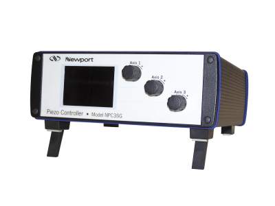
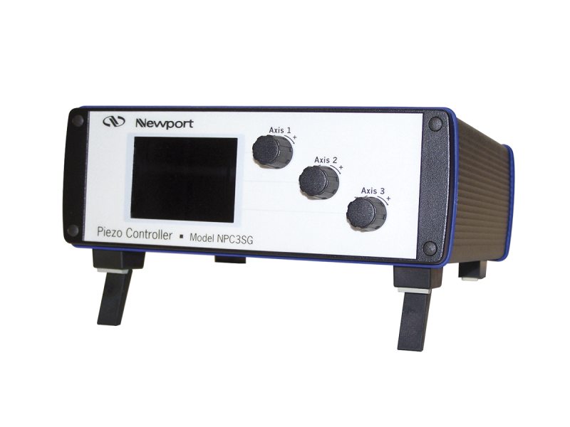
The NPC Piezo Stack Controller series allow for control of up to 3 axes. The models *DIG *SG are designed for NanoPositioning products with strain gauge position feedback. They support open-loop (voltage) control and closed loop (position) control. In both cases, the monitor output provides a voltage signal proportional to the actual position (0-10V). Since the open-loop response of a piezoelectric element is faster than the closed-loop response, it can be advantageous for certain applications to use open-loop voltage control while monitoring the position via the monitor output. The model NPC3 and NPC1USB operate in open-loop only and do not read feedback from strain gauges.

Dynamic Closed-loop Performance

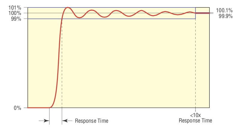
The dynamic properties of a closed-loop piezo system depends on many factors, most important, the payload and the spring constant of any material the piezo system is pushing against. A servo loop maintains accurate position control, and the settings of the control loop filters have a significant impact on the dynamic performance and stability of the system. Unfortunately, high dynamics and high position stability conflict with each other, particularly when a large load needs to be moved. In general, Newport electronics are optimized for the highest achievable positioning accuracy under static conditions and over a wide load range. Upon request, an optimization of the control loop parameters that is based on the mass, inertia, rigidity of the payload, and an applied external force, can be made according to application's operating bandwidth and stability requirements. The table below summarizes the closed-loop step response times for all Newport NanoPositioning products with strain gauge feedback and standard controller settings. This step response time is adjusted as part of the factory acceptance test. The closed-loop step response time is defined as the maximum time required for any displacement (up to a step equal to the nominal closed-loop range) with a stability of ± 1%, a maximum position overshoot of 10% and damping that ensures better than ± 0.1% stability, measure after 10X the step response time. The step response time is adjusted with the listed test load. For the NanoFocusing Objective stage NPO100SG, for example, a 100 µm step displacement with ± 100 nm stability and a 135 g objective lens can be reached within 80 ms. As mentioned above, considerably different performance may be possible with custom controller settings.

Dynamic Open-loop Operation

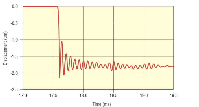
In open-loop, a piezoelectric actuator can reach its nominal displacement in approx. one third of the period of its first resonant frequency. The resonant frequencies for all our devices are provided for different loads, see specifications on the individual product pages. For loads in between, a linear relationship between the load and the resonant frequency can be assumed. Example: With 105 g load, the resonant frequency of the NanoPositioning linear stage NPXYZ100 in z-direction is 250 Hz. It can reach its nominal displacement within 1.3 ms. When the stage is excited with a sharp electrical pulse, the stages resonant frequency will be excited resulting in position overshoots with a damped oscillation. Hence, shorter electrical pulses may result in higher super-elevation, but not in shorter rise times.

Open Loop Boundary Conditions

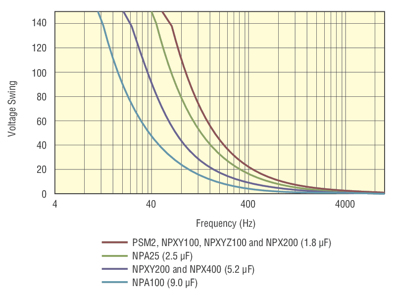
Another boundary for fast open-loop operation is the current that can be provided by the piezoelectric amplifier. The diagram displays the max. sinusoidal frequency which can be supplied by the NPC3 and NPC3SG amplifiers as a function of the capacitance of the piezoelectric transducer and the voltage amplitude. For other models please see user manual for drive frequency curves.

Sensor Pre-amplifier and SIC

All Newport NanoPositioning devices with strain gauge feedback feature a sensor identification chip (SIC) and a calibrated pre-amplifier that is housed inside the device, or in a small box that is part of the cable. This pre-amplifier ensures high sensor signal homogeneity that results in considerably higher position accuracy compared to alternative designs where the pre-amplification is done inside the amplifier only. But the calibrated pre-amplifier has even more advantages. In cases when an actuator has to be replaced, there is no need to re-adjust the electronics as long as it is the same actuator type. The SIC contains all relevant information including model type, travel range, etc., and ensures a seamless integration and operation.

Manual Control Mode

In manual control, the output voltage/position can be set for each channel separately using the 30 step encoder knob on the front panel (where applicable). Pressing the knob toggles between open-loop and closed-loop. The last setting is saved in memory and is loaded after restart. 

Analog Control Mode

Analog control: In analog control, the output voltage/position is controlled by an analog signal applied to the modulation input (0V-10V). In open-loop control, 0 V corresponds to -20V output voltage, and 10V corresponds to 130 V output voltage. In closed-loop control, 0 V corresponds to zero displacement and 10V corresponds to the maximum nominal closed-loop displacement. Analog control and manual control can be used simultaneously and are additive.

Computer Control Mode

Computer control: For convenient computer control, an RS232 and USB interface are provided. The interface resolution is 16 Bit. In computer control, the DC-offset potentiometer (manual control) and analog input are inactive. Commands can be issued via HyperTerminal.