Specifications

Features

Automate Laser Diode Control and Testing

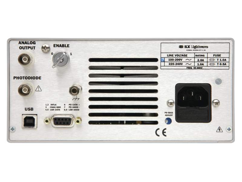
Remote instrument operation is available on all LDX-3500B Series Laser Diode Drivers through a USB 2.0 serial interface. All instrument controls and functions are accessible through the serial interface for easy remote programming and control in automated test and control systems where repeatable and accurate test sequencing, measurements, and data handling are required. Installation software available with each instrument in a very easy to read and change format facilitates instrument set up and control in minutes. Through this software, instrument controls are organized similar to the front panel for easy, intuitive instrument remote control and monitoring. Also included is an example L-I application written in C# with the source code for reference. Whether the application is data intensive L-I testing or control in R&D manufacturing testing, remote operation of the LDX-3500B saves time and ensures systematic data collection and instrument operation.

Ease of Operation

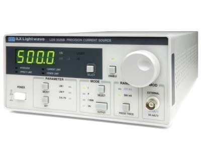
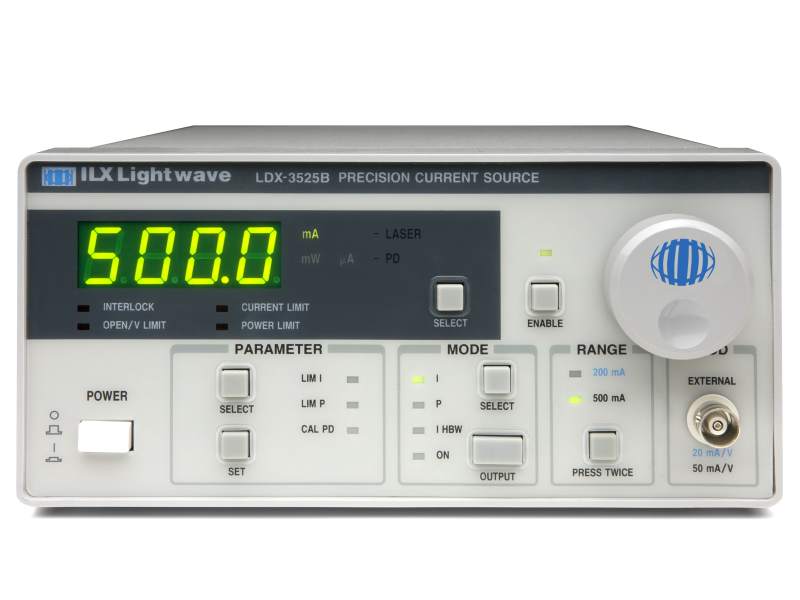
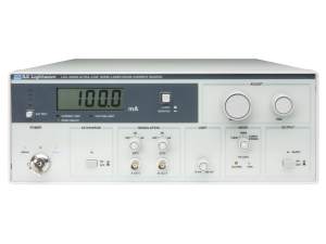
The LDX-3500B Series Laser Diode Drivers are microprocessor controlled instruments. The front panel of the LDX-3500B Series was designed for quick and easy instrument operation and information display. A bright five digit, green LED display is easy to read from a distance, even with laser safety glasses Parameters and instrument modes are grouped without confusing multi-function keys. Informative error indicators such as open circuit, current and power limit let the user resolve set-up and operational problems quickly.

Precision Laser Diode Testing

Each LDX-3500B Series Laser Diode Driver was designed as a current source specifically for low to high power laser diodes. Stable, precision low noise current control with a set point accuracy of 0.1% is delivered to the laser during R&D or manufacturing testing including L-I testing, qualification testing or automated testing and control applications.

Simplify Routine Maintenance

The LDX-3500B architecture simplifies routine maintenance; calibration of the laser current source can be performed via the front panel or remotely through the USB 2.0 interface, without opening the instrument up or manual adjustments. A calibration mode is entered through unique push button combinations or control commands, and all calibration data is easily entered via the front panel with the adjust knob or commands. Calibration data is automatically stored in on-board non-volatile memory.

A Choice of Laser Diode Control Modes

Each laser diode driver’s laser current source can be operated in one of three modes:

  • Constant current, low bandwidth: optimized for DC operation and offers improved laser protection and lowest noise.
  • Constant current, high bandwidth: the output stage supports up to 1MHz modulation frequency for dithering the laser current in power and wavelength tuning applications.
  • Constant optical power: provides constant optical power operation of your laser diode by measuring the photocurrent from the laser diode’s rear-facet photodiode or an external photodiode in a feedback control loop to the current source.

Setting the Standard in Laser Diode Protection

Laser diodes are extremely sensitive to electro-static discharge, excessive current levels, current spikes, or transients from power surges or other laboratory equipment. One of the most important features we have implemented into each instrument is the ILX Lightwave proven laser diode protection standards. These standards have led to advanced protection features such as independent hardware current limits, a slow-start ramping technique, and isolated supplies. A "clamping" circuit prevents the limits from being exceeded under any condition including current modulation. An output shorting switch provides a safe method of switching the output on and off during operation while protecting the laser during load/unload or connect/disconnect operations. Also, if the instrument senses an open circuit, the output will immediately shut off followed by the illumination of the appropriate fault indicator. During AC power-up, the laser is protected from current transients by power line filters and double shielded transformers. Transients from normal instrument operation such as output on/off have been thoroughly tested and minimized as well as transients from inadvertent instrument operation (such as mode switching). For more information about these protection features, please see our “Protecting Your Laser Diode" application note.