Laser Diode Technology

The commercial and industrial use of laser diodes has dramatically increased recently. The optical characteristics, small size, and ruggedness of laser diodes have allowed many new uses to be commercialized. The output of laser diodes is very bright considering their small size. Today, hundreds of watts of power are commercially available from laser diodes operating under continuous wave (CW) conditions in packages as small as a few cubic inches. This characteristic makes these devices suitable for cable TV transmission, high definition TV (HDTV) development, and medical applications.

In addition, compared to other types of lasers, laser diodes use very little power. Most laser diodes operate with voltage drops of less than 2 V with power requirements determined by their current setting. Overall efficiencies greater than 30% are typical in the case of laser diodes.

Since laser diodes are made of semiconductor materials, they do not require the fragile glass enclosures or mirror alignment typical of gas lasers. The resulting ruggedness and small size allow laser diodes to be used in environments and spaces in which other types of lasers cannot operate.

Coherence and single wavelength characteristics of laser diodes enable the outputs of these devices to be focused to a diffraction limited spot size. The size of the resultant spot is dependent on the wavelength of the laser - the shorter the wavelength of light, the smaller the size of the spot that can be generated. Operation at shorter blue and UV wavelengths makes smaller spot sizes possible, consequently allowing more information to be stored on optical disks at a higher density.

Another advantage of laser diodes is that they can be directly modulated at high frequencies. By modulating the drive current, the output of the laser diode is modulated with frequencies up to several GHz in high-speed data communications.

Low-Power Laser Diodes

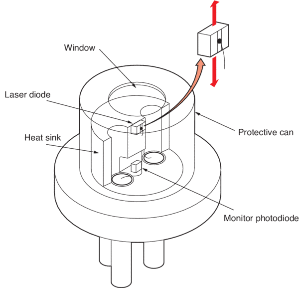
Low-power laser diodes come in a variety of packages. Most have a monitor photodiode integrated with the laser diode. Generally, laser diodes emit light from both ends of their cavity. By monitoring the rear facet output beam of the laser diode, one can maintain the laser at a constant power level. For power levels in the range of 1 W or less, the most common package used is the TO-Can style and is available in either a 5.6 mm or 9 mm diameter base (Figure 1). Other packages include TO-3 packages for higher power laser diodes (>1 W).

Laser diode and monitor photodiode arrangement in can-style package
Figure 1. Laser diode and monitor photodiode arrangement in can-style package.

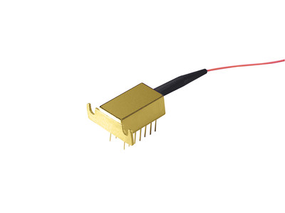
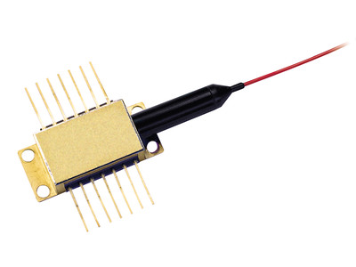
Telecommunication laser diodes come in either butterfly or DIL (Dual-In-Line) 14-pin packages (Figure 2). Most include both a thermo-electric cooler (TEC) module, and all include a mounting plate for heat dissipation.

17-199-S
Figure 2a: Dual-in-line 14 pin telecommunication laser diode
16-072-S
Figure 2b: Butterfly package telecommunication laser diode

Many other packages are used including coaxial cans for pulsed laser diodes and a variety of fiber pigtailed laser diodes with CD/DVD style laser diodes integrated into a custom designed housing that includes focusing optics and a fiber output.

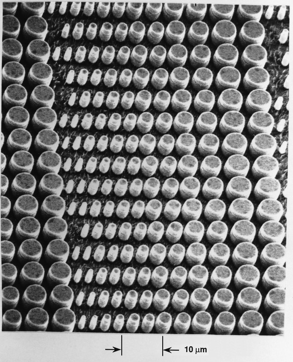
Other structures include Vertical Cavity Surface Emitting Lasers (VCSEL) and Master Oscillator Power Amplifier (MOPA) lasers. VCSEL laser diodes (Figure 3) can be fabricated in 2-D arrays for use in optical computing, printing and communications. Their laser structure has a circular aperture allowing the output beam to be easily collimated using a simple spherical lens. MOPA lasers have been developed to increase the output power of single-mode laser diodes while maintaining a narrow line width. These laser diode structures have an oscillator section that produces a very narrow spectral output, and an integrated power amplifier section that increases the output power without affecting the spectral output.

Scanning electron micrograph of a 2-dimensional VCSEL array
Figure 3. Scanning electron micrograph of a 2-dimensional VCSEL array. Photo by Axel Scherer, courtesy of Picolight, Inc., Boulder, Colorado.

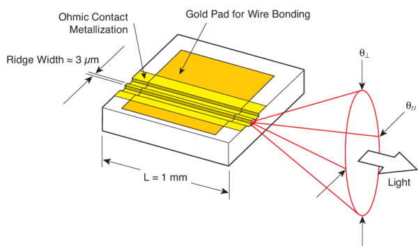
Applications requiring narrower spectral linewidths need structures that confine the laser's oscillations to a single-mode. Index guided devices provide the necessary confinement that result in single-mode output beams with little or no astigmatism. However, divergence of the light emitting from a laser diode is very pronounced with full width half maximum (FWHM) angles of up to 40 degrees in the perpendicular axis (θ) and 10 degrees in the parallel axis (θ||). This divergence results in a rapidly expanding elliptical cone. Gain-guided laser diodes tend to have greater differences between the two angles than index-guided laser diodes. Figure 4 illustrates beam divergence in the theta parallel and theta perpendicular axes.

Schematic representation of an index guided device and its diverging output beam profile
Figure 4. Schematic representation of an index guided device and its diverging output beam profile.

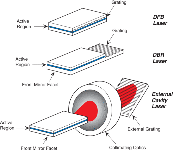
Single frequency laser diodes are another interesting member of the laser diode family. These devices are now available to meet the requirements for spectroscopy and high bandwidth communications. Other advantages of these structures are lower threshold currents and lower power requirements. One variety of this type of structure is the distributed feedback (DFB) laser diode (Figure 5). It has been developed to emit light at fiber optic communication wavelengths between 1300 nm and 1550 nm.

Various single frequency semiconductor lasers: DFB, DBR, and external grating devices
Figure 5. Various single frequency semiconductor lasers: DFB, DBR, and external grating devices.

Since lasers emit light over a narrow wavelength range, they can also be used for sensing and spectroscopy. Examples include the detection of trace gases, and elements that react to light at very defined wavelengths. By proper selection and wavelength tuning of a laser diode one can detect these elements.

High-Power Laser Diodes

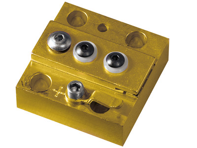
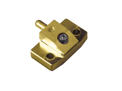
More recently high-power laser diodes operating in the wavelength range of about 0.8–1.1 micron have been getting much attention due to their widespread applications. These lasers are used in optical pumping of solid-state lasers, such as the Nd:YAG, replacing traditional flash lamp designs. High-power laser diodes are tuned to the absorption band of the dielectric crystal resulting in much more efficient pumping of the laser rod, from which a high-power focused coherent beam of light is emitted. This beam can then be used in a variety of industrial, medical, and military applications. Laser diodes have been developed to match the absorption bands of a variety of dielectric crystals in a broad wavelength range. Figure 6 shows two common variations of high-power laser diode packages.

17-188-S
Figure 6a: Bar-Type high-power laser diode package style
17-187-S
Figure 6b: S-Type high-power laser diode package style

In addition to applications involving the pumping of solid-state laser rods, high-power laser diodes are also very useful for fiber optic telecommunication purposes. In these applications, a high-power laser diode operating at the wavelength of 980 nm is used as a pump source for erbium doped fiber amplifiers. Such optical amplifiers are used in direct optical amplification of the 1550 nm wavelength telecommunication signals propagating along the long haul telecommunication lines. In this fashion, the need to use electrical amplifying circuits is eliminated and the optical signals are directly amplified, with greater efficiency, and without the need to convert the light signal to an electrical signal and back.

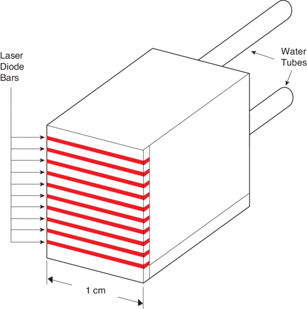
By stacking several high-power laser diode bars on top of one another, it is possible to make stacked laser diode arrays (Figure 7) with output powers potentially in the range of kilowatts. Such devices open up a wide range of new possibilities in such applications as industrial welding and precision cutting of metals and various other materials.

Schematic diagram showing a typical high-power stacked bar laser diode package
Figure 7. Schematic diagram showing a typical high-power stacked bar laser diode package.

Opto-Electronic Characteristics of Laser Diodes

Threshold Current and Threshold Current Density

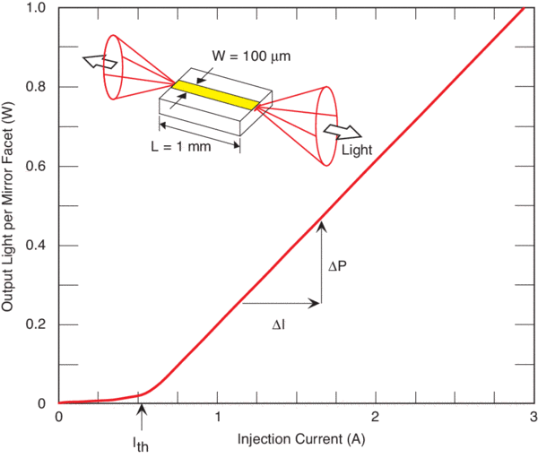
Perhaps the most important parameter of laser diodes to be measured with Laser Diode Instrumentation is the degree to which they emit light when current is injected into the device. This generates the Output Light vs. Input Current Curve, more commonly referred to as the L.I. Curve shown in Figure 8. As the injected current is increased, the laser first demonstrates spontaneous emission that increases very gradually until it begins to emit stimulated radiation, which is the onset of laser action. The first parameter of interest is the exact current value at which this phenomenon takes place. This is typically referred to as the threshold current and is denoted by the symbol Ith. It is generally desirable that the threshold current be as low as possible, resulting in a more efficient device. Thus, a threshold current is one measure used to quantify the performance of a laser diode.

A typical Light vs. Current (L.I.) curve associated with a high-power laser diode
Figure 8. A typical Light vs. Current (L.I.) curve associated with a high-power laser diode.

Ith represents the threshold current at which the device begins to lase. The efficiency of the laser in converting electrical power to light power is determined by the slope of the L.I. curve, denoted by the change in output power over the change in current (ΔP/ΔI). The inset schematically shows a broad area (100 µm wide stripe) laser diode emitting radiation from both its front and back mirror facets.

Threshold current is dependent on the quality of the semiconductor material from which the device is fabricated, and also the general design of the structure of the device waveguide. However, threshold current is also dependent on the size and area of the laser device. One laser diode could demonstrate a much higher threshold current than another device and yet be considered a much better laser. This is because the area of the device can be large. A laser that is wider or longer obviously requires more electrical power to reach the onset of laser action than a laser of a smaller area. As a result, when comparing the threshold current values of different devices, it is more appropriate to talk about threshold current density rather than threshold current. Threshold current density is denoted by the symbol Jth and is determined by dividing the experimentally obtained threshold current value Ith by the area of the laser. It is always desirable for a laser to have a low threshold current density value. Threshold current density is one of the parameters that is a direct indication of the quality of the semiconductor material from which the device is fabricated. In comparing the performance of various laser devices one must compare the threshold current density values rather than the threshold current values. In calculating the current density of the laser, it is necessary to accurately measure the area of the laser through which current is being injected. This is only possible in broad area type lasers with stripe widths on the order of 100 microns or more. In such cases, the area through which the current is flowing is very much the same as the area of the metallic contact of the laser. In cases of ridge lasers the width of the ridge is only a few microns while, due to current spreading, the actual width of the channel through which current is flowing could be considerably more. This makes it impractical to accurately determine current density values in cases of narrow stripe ridge lasers.

Slope of the L.I. Curve

Just as it is desirable to reach laser action at as low a threshold current as possible, it is also desirable to get more and more light out of the device with the expenditure of as little current as possible. In other words, you would want to be able to increase the input current slowly and yet achieve rapid increase in the output light emission. A laser diode, which has a good rate of converting the input electric power to output light power, is obviously a device that is performing well. A direct measure of the ability of the device to do this is the slope of the L.I. curve. This slope is denoted as ΔP/ΔI and has the units of Watts per Amperes (W/A), or in the case of low-power lasers (mW/mA). ΔP/ΔI, which is the slope of the L.I. curve above the threshold current Ith, directly tells us how many Watts of power the laser outputs for every 1 Amp increase in its input current. Other important parameters are typically extracted from measurement of the ΔP/ΔI parameter. These include the External Differential Quantum Efficiency, Internal Quantum Efficiency, and Internal Loss parameters. Please refer to Newport's Application Notes for an in-depth discussion of these topics and the description of the experimental setups and calculation procedures needed to accurately determine the above-mentioned parameters.

Characteristic Temperature

In most applications, the ability of the laser diode to perform well at elevated temperatures is of great interest. This is especially of concern in the case of high-power laser diodes where the amount of power generated causes the device temperature to rise significantly. As a result, it is of utmost importance for the semiconductor crystal to be robust enough so as not to suffer from device deterioration at high temperatures. The characteristic temperature of the laser diode, which is commonly referred to as To (pronounced T-zero), is a measure of the temperature sensitivity of the device. Higher values of To imply that the threshold current density and the external differential quantum efficiency of the device increase less rapidly with increasing temperatures. This translates into the laser being more thermally stable. In order to measure the characteristic temperature of a laser diode it is necessary to experimentally measure the L.I. curve of a laser at various temperatures. The results are then tabulated and the To determined. Typically, people perform these measurements at temperatures ranging from 15 degrees Celsius up to about 80 degrees Celsius, and at 5 or 10-degree increments. Conventional AlGaAs lasers usually have To values above 120 degrees. Please refer to Newport's Application Note 1, Test and Characterization of Laser Diodes for more on this topic including the experimental techniques and calculation methods.

Dynamic Series Resistance

The series resistance of the laser diode is typically determined through calculating the derivative of the voltage versus injection current characteristic curve of the device. One way of doing this is to use a computer program to analytically determine the first derivative of the voltage versus current characteristic curve of the device that is obtained experimentally (more on this topic in Newport's Application Note 1). High series resistance values for a laser diode could be the result of low quality metal ohmic contacts deposited on the two sides of the device. As a result, measurement of the series resistance value can be a means of assessing the quality of the metallic contacts deposited on the laser.

Astigmatism

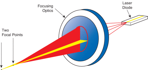
As laser diodes have evolved over the past fifteen years, various structures have been developed with different characteristics. The first laser diodes used gain-guided structures, which are easy to fabricate, resulting in a reliable device at low manufacturing costs. This type of structure supports multiple modes, resulting in multiple spectral lines and astigmatism. Astigmatism is a condition in which the apparent focal points of the two axes do not coincide. It limits the ability to focus the laser beam to a small spot size (Figure 9) and complicates focusing the output beam to a sharp well-defined point.

Schematic diagram showing the problem of astigmatism
Figure 9. Schematic diagram showing the problem of astigmatism.

Polarization

The ratio of the parallel and perpendicular vectors of polarization is called the polarization ratio. Laser diodes can reach polarization ratios of 100 to 1 or more when operated near their maximum output power ratings.

Collimation of Laser Diode Beams

Since the output of a laser diode is highly divergent, special collimating optics are required. Either molded aspheres or multiple element glass lenses have been traditionally used to collimate the output. These collimators< typically have a numerical aperture of 0.5 or better to collect the entire laser output beam.

Using lenses, the output light of a laser diode can be formed into a collimated beam with little divergence. Such a highly directional collimated beam of intense light has many uses, such as in the alignment of large structures in civil engineering or in the read head of CD players. Also, due to the coherent nature of laser light, its properties stay the same in space and time. This is useful in interferometric measurements of material deformities. If a gain-guided laser diode beam is collimated or being focused, then a cylindrical lens is used to account for astigmatism. A long focal length lens is used to compensate for the astigmatism and then the collimating lens can provide a beam that has little divergence in both axes.

The collimated beam is still elliptical and can be circularized using an anamorphic prism pair. Either the major axis is compressed or the minor axis is expanded to make a circular beam. Focusing the output beam of a laser diode into a single-mode fiber will also result in a circularized output. The fiber acts as a filter since only one mode propagates down the fiber. The output from the fiber is a circular, conical beam with a highly Gaussian shape, and low numerical aperture (N.A. <0.1). A simple spherical lens is used to complete the collimation.

Newer techniques for collimating laser diodes include micro lenses and diffraction optics, both resulting in very compact packages. Micro lenses are bonded just in front of the emitting apertures of the laser diode. The complete assembly fits inside the laser diode package. Diffraction optics are manufactured using photolithography techniques that result in high repeatability and extremely low cost in large quantities. The diffraction optics are mounted externally but still result in extremely small laser diode packages.

Spectral Characteristics of Laser Diodes

Optical Spectrum

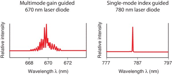
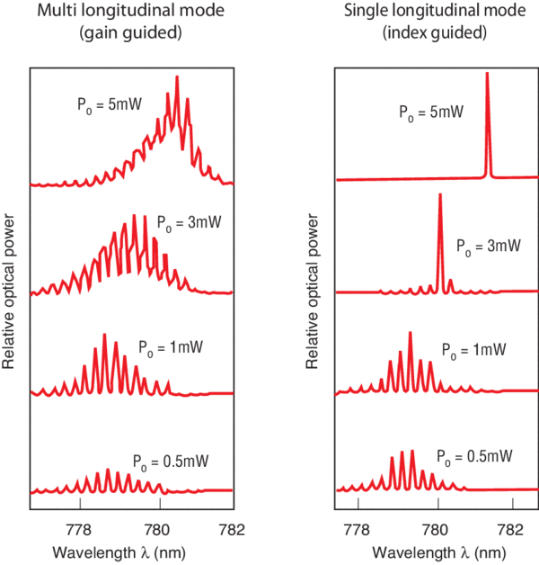
The optical spectrum of laser diodes depends on the particular characteristics of the laser's optical cavity. Most conventional gain or index-guided devices have a spectrum with multiple peaks, while distributed feedback (DFB) and distributed Bragg reflector (DBR) types of devices display a single well-defined spectral peak. Figure 10 shows a comparison between these two spectral behaviors.

Multimode versus single-mode spectra
Figure 10. Multimode versus single-mode spectra.

The number of spectral lines that a laser is capable of supporting is a function of the cavity structure, as well as the operating current. The result is that multimode laser diodes exhibit spectral outputs with multiple peaks around their center wavelength. The optical wave propagating through the laser cavity forms a standing wave between the two mirror facets of the laser. The distance L between the two mirrors determines the period of oscillation of this curve. This standing optical wave resonates only when the cavity length L is an integer number m of half wavelengths existing between the two mirrors. In other words, a node must exist at each end of the cavity. The only way this can take place is for L to be exactly a whole number multiple of half wavelengths λ/2. This means that L = m(λ/2), where λ is the wavelength of light in the semiconductor matter and is related to the wavelength of light in free space through the index of refraction n by the relationship λ = λo/n. As a result of this situation, there can exist many longitudinal modes in the cavity of the laser diode, each resonating at its distinct wavelength of λm = 2L/m. From this you can note that two adjacent longitudinal laser modes are separated by a wavelength of Δλ = (λo)2/2nL. Even single-mode devices can support multiple modes at low output power as shown in Figure 11. As the operating current is increased, one mode begins to dominate until, beyond a certain operating power level, a single narrow line width spectrum appears.

Effects of operating current level on the output spectrum
Figure 11. Effects of operating current level on the output spectrum.

Center Wavelength Changes with Temperature

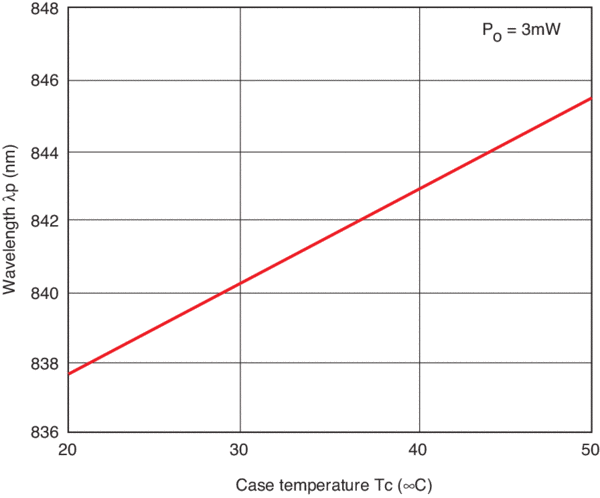
The center wavelength of a laser diode is directly proportional to its operating temperature. There is a linear relationship between temperature and center wavelength (as shown in Figure 12). As temperature increases, so does the center wavelength of the laser diode. This characteristic is useful in spectroscopy applications, laser diode pumping of solid state lasers and erbium-doped fiber amplifiers, where the wavelength of emission of the laser diode can be accurately temperature-tuned to the specific properties of the material with which it is interacting.

Effects of temperature on laser diode center wavelength
Figure 12. Effects of temperature on laser diode center wavelength.

Mode Hopping

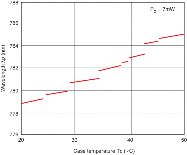
Single-mode lasers exhibit a phenomenon called mode hopping (Figure 13), in which the center frequency of the laser diode hops over discrete wavelength bands and does not show continuous tuning over a broad range. One can change the wavelength where the discontinuities take place by making small adjustments to the drive current. When selecting a specific laser diode for an application requiring a specific wavelength, such as spectroscopy, mode hopping must be taken into account when temperature tuning the device.

Mode hopping observed while temperature tuning a single-mode laser diode
Figure 13. Mode hopping observed while temperature tuning a single-mode laser diode.

Laser Diode Lifetime Requirements

The operating lifetime of a laser diode is dependent on its operating temperature. A high quality laser diode operating at 20°C could have a lifetime in excess of 100,000 hours. Failure of a laser diode is usually defined as the point in time when the operating current required to maintain a specified output power is increased by some percentage (50%) of the initial current. The temperature measured is the case temperature of the laser diode package. The manufacturer usually provides lifetime curves for specified output powers.

Effects of Electrostatic Discharge on Laser Diodes

Laser diodes are extremely sensitive to Electrostatic Discharge (ESD) and must be handled with care. When handling a laser diode, always follow the manufacturer's instructions for removing the laser diode from its shipping container. You must take care to ensure that your laser diode is properly protected during handling. Generally, operators must be properly earth grounded and should use conductive finger guards when handling a laser diode. All equipment must be properly earth grounded. You should always closely follow the manufacturer's specifications and instructions for proper heat sinking. It is strongly recommended not to solder directly to a laser diode package or its electrical leads. It is best to make all electrical connections to a socket, such as a transistor socket, into which the laser diode can be inserted.

Current Source Requirements for Laser Diodes

Laser diodes require a low noise current source called a laser diode driver. Standard power supplies usually operate as constant voltage sources and do not have the necessary protection circuits that laser diodes need. They are also too noisy for most laser diode applications. Also, laser diodes are easily damaged from voltage and current fluctuations and transients. Specialized circuit designs have been developed to protect laser diodes from being damaged. The first stage of protection includes input AC power filtering and high-speed transient detection circuits. Low voltage and AC line transient detection circuits, and shielded transformers, provide additional protection.

Momentary internal transients within the power supply may occur when the output current is turned on or off. Laser diode drivers should have the output to the laser diode shorted whenever the output is turned off. This is accomplished by using redundant FET and relay shorting devices across the output. During the turn-on phase, these shorting devices protect the laser diode from both voltage and current transients. After a delay of several seconds, the output current slowly ramps up over several milliseconds to several hundred milliseconds to the set point value.

Another necessary feature of laser diode drivers is the independent current limit. This limit is set separately from the set point value and overrides any condition that may cause the output current to exceed the laser diode's maximum current rating. Some current sources utilize a software programmable power limit that works similarly to the current limit. While the current limit is hardwired, the power limit must be programmed and one must therefore know the responsivity of the photodiode to properly set the power limit. Both work independently to safeguard your laser diodes.

Temperature Control for Laser Diodes

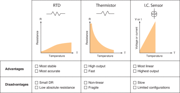
Since many parameters depend on the temperature of the laser diode, it is important to set and maintain a stable temperature using a thermo-electric temperature controller. Most laser diode applications use Thermoelectric (TE) coolers based on the Peltier Effect to maintain a constant temperature. TE modules are semiconductor “heat pumps” that move heat from one side of the device to the other. Depending on the direction the current flows through the TE cooler, you can either heat or cool a laser diode. Several types of temperature sensors are used: thermistors, I.C. sensors, and platinum resistive temperature devices (RTDs). The most commonly used is the thermistor because of its small size and fast response time. Thermistors and RTDs are nonlinear resistance devices. Both require a small accurate current source to bias them. Changes in temperature result in resistance changes, with the voltage drop across the device proportional to temperature. Each device has a characteristic equation that converts resistance to temperature. The Steinhart-Hart equation is used to convert a thermistor's resistance to temperature and uses two or three constants depending on the accuracy required.

Comparison of commonly used temperature sensors
Figure 14. Comparison of commonly used temperature sensors.

I.C. sensors are linear devices whose outputs can easily be converted and displayed in °C. Although they are linear, they are not as accurate as thermistors. Figure 14 summarizes each temperature sensor and its advantages. RTDs are primarily used where one needs an extremely stable sensor for very long-term and accurate temperature controlled applications. The major drawback of RTDs is their small resistance change, which makes it difficult to measure small absolute temperature changes.

Thermistors, on the other hand, have extremely large resistance changes, making it easy to measure small changes in temperature. They are also the smallest of the three types of sensors, which make them ideal candidates for integration into laser diode packages. Laser diode packages with integral TE coolers use a 10kΩ thermistor as the temperature-sensing device.

Test and Characterization of Laser Diodes

It is often necessary to quantitatively assess the quality, performance, and characteristics of laser diodes. This is done through performing a series of experiments and obtaining various parameters from which we can determine how well the laser diode is performing. It is then possible to establish whether the laser diode meets the desired specifications.

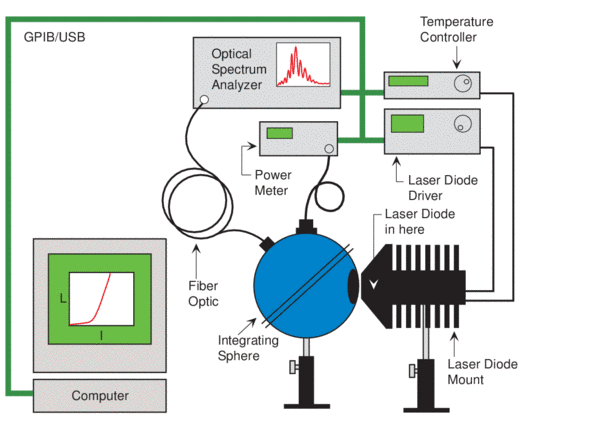
The centerpiece of this experimental setup is the laser diode mount and the Integrating Sphere Detector System. The Laser Diode Mount is designed to provide simple air-cooling for high-power laser diodes.

Figure 15 shows an example of an experimental laboratory setup that can be used to perform full characterization of high-power laser diodes accurately and rapidly. This setup can be fully automated by using a PC and control software such as LabView for full automation of the instrumentation control and data acquisition.

A typical computer controlled laser diode test and characterization setup
Figure 15. A typical computer controlled laser diode test and characterization setup.

In laser diode measurements, the use of an integrating sphere setup is absolutely necessary when performing precise measurements of the output light power. Laser diodes have a highly divergent beam profile and the use of an integrating sphere ensures that all of the light emitted by the laser diode is collected and measured. In addition, it makes the measurement insensitive to exact detector positioning. The signal generated by the detector is then measured with a calibrated optical power meter. This setup makes it possible to accurately measure the output light of laser diodes of various wavelengths. The Optical Measurement System is generally computer controlled using GPIB or USB.

In addition, the Integrating Sphere could be equipped with a fiber optic port. This is used for sampling the light and channeling it to the input of an optical spectrum analyzer. In this fashion, it is possible to perform simultaneous measurements of the laser diode optical spectrum and peak wavelength of emission, in addition to the L.I.V characteristics.

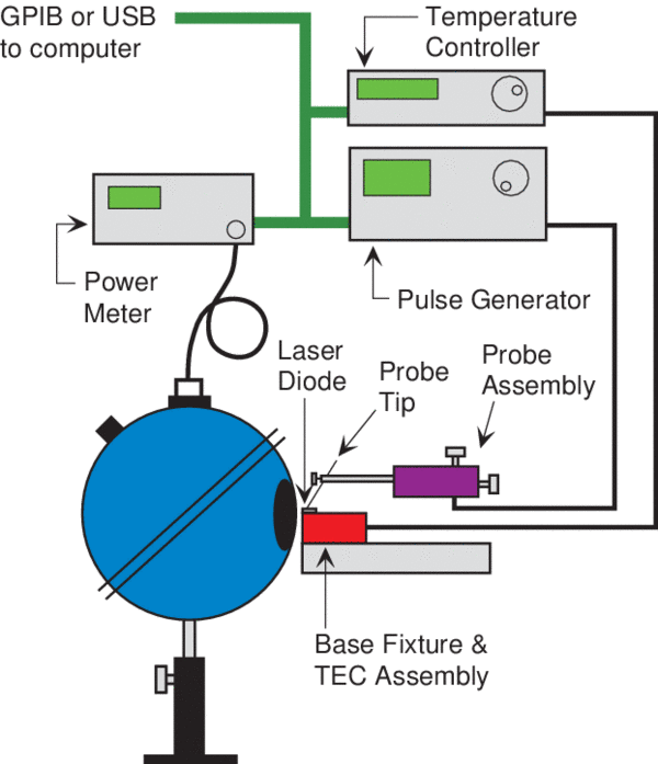
The process of packaging laser diodes is very labor intensive and an expensive part of the manufacturing of these devices. Because of this, it is generally necessary to fully assess the quality of the semiconductor wafers from which the laser diodes are fabricated prior to full device manufacturing. In addition to a series of structural, electrical, and optical characterization tests that the wafers undergo, most often broad area lasers are also processed from the wafers and then tested in order to determine whether the wafer is a “Device Quality Wafer” or not. This prevents low quality material to be used for manufacturing of devices. Since these devices are tested without being bonded on heat sinks, and are not fully packaged, it is absolutely necessary that all testing and characterization is done under low duty cycle pulse current conditions. In this fashion, heat dissipation is not an issue and it is possible to determine the characteristics of the devices without the need to fully package them. Figure 16 shows the experimental setup for the characterization of laser diodes under pulse condition. Note that in this case, a probe station is used to probe and inject current into each device and the laser diode driver is a current pulse generator.

Typical experimental setup using a probe station arrangement for pulse characterization of laser diode chips and laser diode bars not mounted onto heatsinks
Figure 16. Typical experimental setup using a probe station arrangement for pulse characterization of laser diode chips and laser diode bars not mounted onto heatsinks.

Using such experimental setups it is possible to perform full laser diode testing and characterization; leading to the determination of such significant parameters as the threshold current and threshold current density, external differential quantum efficiency, internal quantum efficiency, internal loss, spectrum and peak wavelength of emission, series resistance, and characteristic temperature.

Related Topics

Lasers

Laser Diodes and LEDs